- Home
- Product
- Solution
- About
- Download
- Glossary
- News
- Contact Us
- language
Features
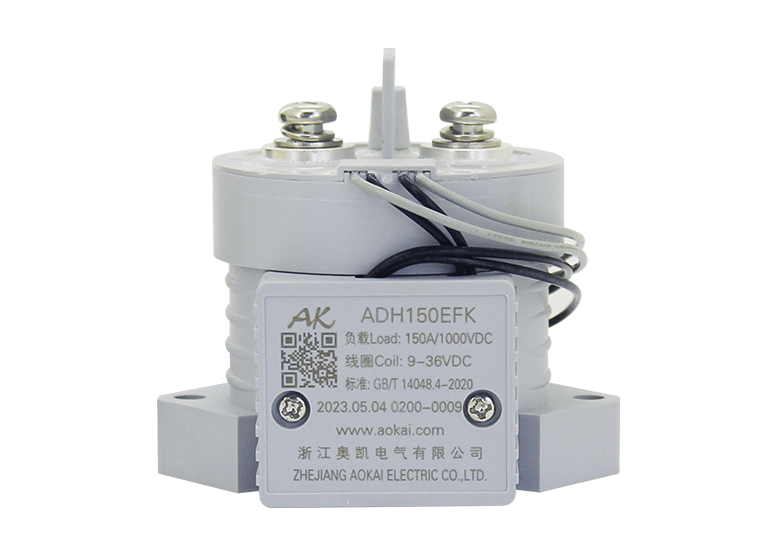
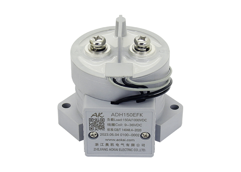
1、Sealed with high-strength epoxy resin, no risk of arc leakage, ensuring no fire or explosion within the service life.
2、Potting with mainly nitrogen inert gas improves arc extinguishing performance and effectively prevents contact oxidation and burnout. The contact resistance is low and stable, and the contact part can meet the IP67 protection grade.
3、150A 85ºC long time current carrying capacity.
4、The insulation resistance reaches 100MΩ (1,000VDC), and the withstand voltage between the contact and the coil is 3.5kV.
5、Compliant with IEC 60664-1, GB/T14048.1 and GB/T14048.4 requirements.
6、Compliant with RoHS (2015/863/EC) and REACH (1907/2006/EC) requirements.
7、Safety certificate: CE, CCC, RoHS.
Main Contact Specification
Contact Arrangement | 1K(1NO) |
Contact Polarity | Non-polarity |
Contact Resistance | ≤0.5mΩ(at 150A) |
Max. Switching Voltage | 1000VDC |
Max. Breaking Current | 1,500A (320VDC) 1次(Ops) |
Electrical Endurance (Resistive Load) | 10,000次(Ops) (1,000VDC, 150A) |
15,000次(Ops) (750VDC, 150A) | |
20,000次(Ops) (500VDC, 150A) | |
Mechanical Endurance | 300,000次(Ops) |
Withstand Current | 150A, Continuous |
200A,60min | |
300A,5min | |
400A,1min | |
Temperature Rise | Main Contact Temperature Rise≤45K(35mm²,150A Continuous) |
Performance Parameter(at23℃)
Pickup Voltage | See Coil Parameter Tables | |
Dropout Voltage | See Coil Parameter Tables | |
Pickup Time | ≤25ms | |
Contact Bounce Period | ≤5ms | |
Dropout Time | ≤6ms | |
Dielectric Strength | Between Main Contacts | 12,000VDC 1min |
Between Main Contact and Coil | 3500VDC 1min | |
Insulation Resistance | Initial State | 100MΩ 1min c |
After Electrical Life | 50MΩ 1min | |
Shock | Stability | 20g (Power On) |
Strength | 50g | |
Vibration | 10g, 10~500Hz, 1/2 Sine Wave (Power On) | |
Relative Humidity | 5%~95%RH | |
Temperature | -40℃~85℃ | |
Load Terminal | M6 Internal Thread | |
Weight | 约About 460g | |
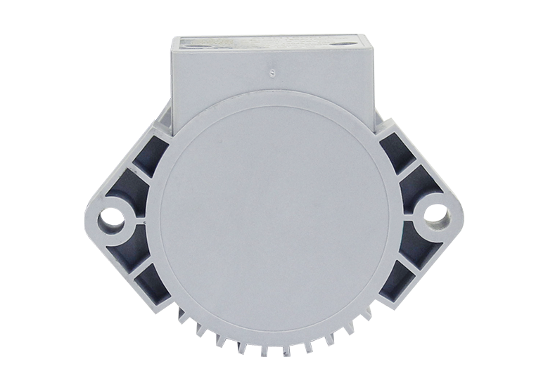
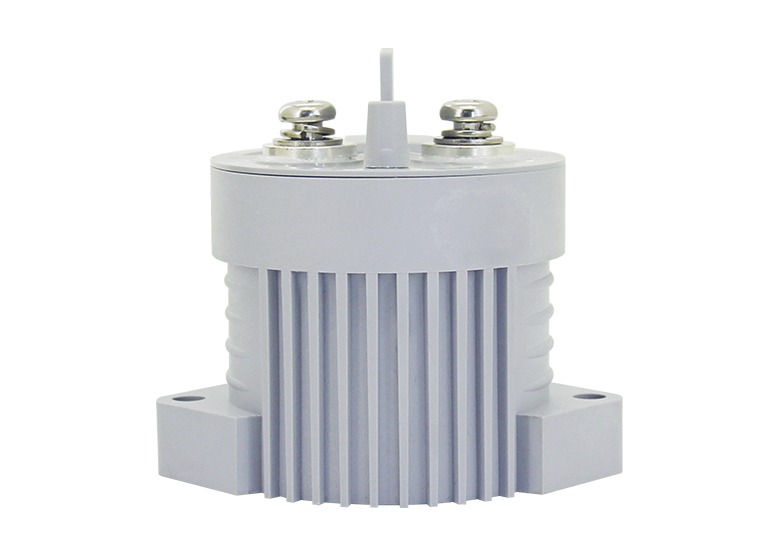
Dimension | 80x65.5x72.5mm |
Auxiliary Contact Parameter
Aux. Contact Arrangement | FK/FB/FZ (1NO/1NC/1CO) |
Aux. Contact Rated Current | 5A |
Aux. Contact Max. Breaking Voltage | 120VDC |
ADH150E Coil Parameter
Coil Voltage | Pickup Voltage VDC | Dropout Voltage VDC | Coil Resistance | Starting Power | Holding Power |
9-36V | 9-36V | 5-7V | 3.5Ω±10% | 25W±10%(<100ms) | 2W±10% |
ADH150D Coil Parameter
Coil Voltage | Pickup Voltage VDC | Dropout Voltage VDC | Coil Resistance | Starting Power | Holding Power | |
Starting | Holding | |||||
12V | ≤70%Us | 5%-40%Us | 2.5Ω±10% | 48Ω±10% | 60W±10% | 3W±10% |
24V | ≤70%Us | 5%-40%Us | 10Ω±10% | 190Ω±10% | 60W±10% | 3W±10% |
48V | ≤70%Us | 5%-40%Us | 40Ω±10% | 768Ω±10% | 60W±10% | 3W±10% |
60V | ≤70%Us | 5%-40%Us | 62.5Ω±10% | 1200Ω±10% | 60W±10% | 3W±10% |
72V | ≤70%Us | 5%-40%Us | 90Ω±10% | 1730Ω±10% | 60W±10% | 3W±10% |
ADH150DE Coil Parameters
Coil Voltage | Pickup Voltage VDC | Dropout Voltage VDC | Coil Resistance | Starting Power | Holding Power | |
Starting | Holding | |||||
12V | ≤70%Us | 5%-40%Us | 2.5Ω±10% | 48Ω±10% | 60W±10% | 3W±10% |
24V | ≤70%Us | 5%-40%Us | 10Ω±10% | 190Ω±10% | 60W±10% | 3W±10% |
48V | ≤70%Us | 5%-40%Us | 40Ω±10% | 768Ω±10% | 60W±10% | 3W±10% |
60V | ≤70%Us | 5%-40%Us | 62.5Ω±10% | 1200Ω±10% | 60W±10% | 3W±10% |
72V | ≤70%Us | 5%-40%Us | 90Ω±10% | 1730Ω±10% | 60W±10% | 3W±10% |
ADH150W Coil Parameter
Coil Voltage | Pickup Voltage VDC | Dropout Voltage VDC | Coil Resistance | Starting Power | Holding Power |
32-96V | 32-96V | 16-20V | 40.5Ω±10% | 25W±10%(<100ms) | 2W±10% |
Model Coding
Outline Installation Dimension Drawing
Without Auxiliary Switch
With Auxiliary Switch
Wiring Diagram
Product Packaging Specifications
Product Model | Packaging | Min. QTY of Inner Packaging | Carton Size (LxWxH cm) | Net Weight/PCS (Max.) g | Total QTY (pcs) | Net Weight (Max.) kg | Gross Weight (Max.) kg |
ADH150EFKG | Pearl Cotton+Carton | 10 PCS/Layer | 53.5x23x20 | 500 | 20 | 10 | 10.8 |
Note:
1、Multiple typical packaging specifications for each product category are only listed as examples for reference.
2、The actual weight of the packaging may fluctuate with environmental temperature and humidity. For specific batch weights, please contact your dedicated sales representative.
Usage Cautions
1、Regarding the application of this product, please select the matching product according to your specific use conditions and environmental requirements when selecting the product. If the requirements are not clearly specified, please contact AOKAI to obtain more technical support.
2、When installing and using this product, regardless of wiring or fixed installation, it is required to use anti-loose spring washers.
3、The torque for installing fasteners should be within the standard range required by this specification. It may cause the unstable installation or damaging the product if the torque is lower than the minimum torque or higher than the maximum torque.
4、Do not install the contactor in places with strong magnetic fields (such as transformers or strong magnets), or close to objects with thermal radiation. It is recommended to use it with a cooling fan.
5、It is forbidden to use the product in an environment with oil pollution, especially before wiring, it will seriously affect the main
terminals conductivity if they are polluted by oil pollution, and affect the product life.
6、It is forbidden to use the product beyond the rated electrical life. When the rated electrical life is reached, although the product can continue to work, there is a risk of failure, explosion, and burning because of non-breaking.
7、When the main circuit voltage is ≥48V, if the H suffix appears on the product label, it means that the main circuit wiring has the current direction, and the "+" terminal or the terminal with red paint must be connected to the positive pole of the power supply (battery).
8、This product cannot be used as a protector, and the circuit must be connected with a protector in series when using.
9、AOKAI only does the resistive electrical life verification and quality assurance. When the product is used in an environment with inductive load or capacitive load, it is recommended that the circuit should be connected in parallel with a surge protection device.
10、After continuous work, restart immediately after disconnection, the pickup voltage will be affected due to the heating state of the product, and it is reasonable that the pickup voltage will increase.
11、It is strictly prohibited to wiring when power on.
12、In principle, please do not use the contactor when it has dropped (height≥30cm).
13、AOKAI reserves the right to change the product. Customers should confirm the content of this specification before the first order, and can ask our company to provide a new specification if necessary.